From Atmosphere to Space
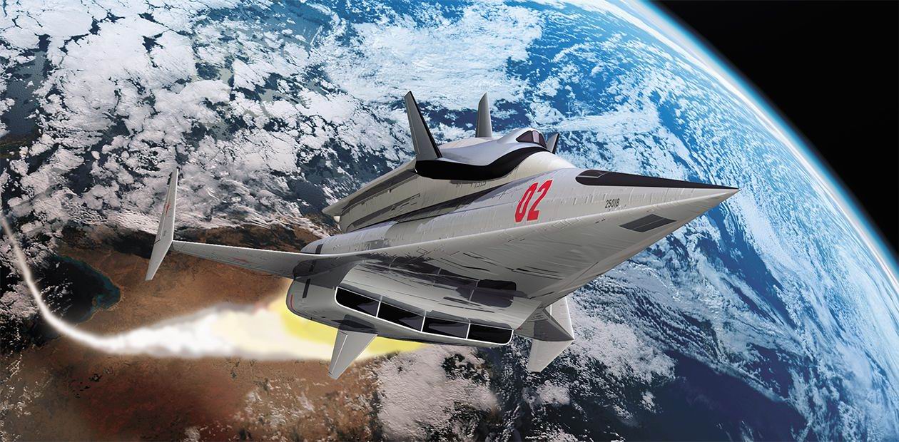
The prospects of using near-Earth space are enormous: communication and navigation systems, environmental monitoring, mineral survey, climate control, production of new materials, etc. All these activities will require setup and operation of multifunctional space stations and, correspondingly, delivery of large amounts of various goods to the near-Earth orbit. The problem of returning spent and dangerous structures from space is becoming more and more urgent, because space debris may incur severe problems. Therefore, it is necessary to develop in the near future revolutionary spacecraft able to cope with increasing transportation flows
Currently existing rocket systems cannot provide transportation of large amounts of cargo to the near-Earth orbit. The reason is not only high cost, but also the long time of launch preparation and a small number of launch pads.
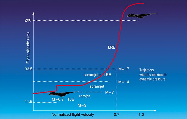
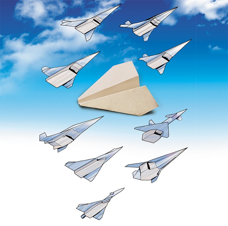
Principally new transportation systems can be developed on the basis of aerospace planes with hybrid propulsion including a ramjet (scramjet) operating on hydrogen and a liquid-propellant rocket engine. By using air for lift force generation and atmospheric oxygen for fuel oxidation on the major part of the atmospheric segment of the boost trajectory, it is possible to reduce appreciably the fuel consumption and launch mass of the aerospace plane. Such a plane can deliver a payload with the mass equal to 3–5% of the takeoff mass to the near-Earth orbit. The delivery cost is estimated by specialists to be 20–50 times lower than that of using rockets.
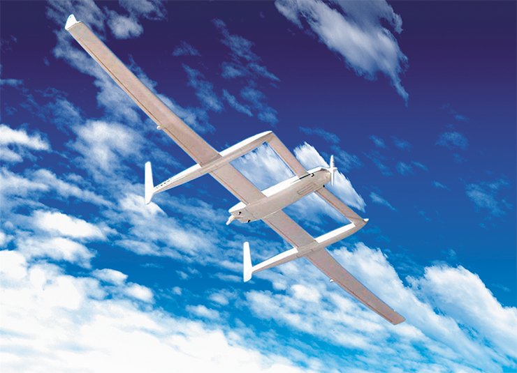
Being an airplane, the aerospace plane has some other advantages over rocket systems. It can take off horizontally from any airfield (there is no need to build complicated and expensive launch sites), and launch preparation takes a much shorter time. The aerospace plane can go into a needed near-Earth orbit by means of maneuvering in the atmosphere rather than in space, which requires much lower fuel consumption. It needs practically no rights of way typically allocated for falling of spent structural elements of rockets. Owing to these advantages, aerospace planes can also be used in prompt rescue operations.
Nevertheless, some special requirements are imposed on this “universal” flying vehicle. In contrast to re-entry modules, the aerospace plane has to perform a rather long-time atmospheric flight with hypersonic velocities, using a permanently operating engine. Therefore, the main difficulties in creating such a flying vehicle are primarily caused by the structure of the thermal and force action of the atmosphere.
During the flight, the maximum pressure on the vehicle is proportional to the squared free-stream flow velocity, and the thermal load at the stagnation point of the vehicle forebody is proportional to velocity raised to the third power. As a result, the thermal load at hypersonic velocities (М*>6) is higher than that at supersonic velocities (М ≤ 3) by a factor of 10 and more; the equilibrium temperature of the thermally insulated shell of the flying vehicle is almost three times higher.
The necessity of solving these problems during the development of hypersonic flying vehicles makes engineers and designers search for principally new ideas, first of all, in the field of materials, aerodynamics, and heat transfer.
Propellant is the heaviest
Investigations aimed at developing a technology of hypersonic flight driven by an air-breathing engine operating on hydrogen have been performed since the 1950s in several foreign countries (USA, France, Germany, Japan, China, and Australia), as well as in the USSR, where two hypersonic systems were under development: Spiral and Buran.
Despite significant achievements reached in the development of aerospace plane technologies, many problems have not been solved. The primary issues in this row are the interrelated problems of the vehicle configuration and propulsion, because the amount of fuel necessary for orbiting is mainly determined by propulsion characteristics and by the lift-over-drag ratio of the aircraft configuration.
Based on investigations of the lift-over-drag ratio of configurations of various flying vehicles and the specific impulse of ramjets with the use of test models, researchers of the Khristianovich Institute of Theoretical and Applied Mechanics of the Siberian Branch of the Russian Academy of Sciences (ITAM SB RAS) calculated the fuel mass necessary for boosting the aerospace plane to the orbital velocity.* It turned out that it should be approximately 70 % of the takeoff mass. The takeoff mass was found to be extremely sensitive to variations of the relative mass of the fuel. For instance, a decrease (increase) in fuel consumption by 1% leads to a corresponding change in the aerospace plane mass by 25%.
Therefore, it is not surprising that rather severe constraints are imposed on the mass of the aerospace plane structure proper. A comparatively large mass of the structure is allowed for multistage systems only, in particular, under the condition of jettisoning of the used structural elements at certain segments of the flight trajectory. In this case, however, the operation conditions of multistage systems become more complicated and the cost increases accordingly.
Heating air
Fuel consumption can be reduced by increasing the lift-over-drag ratio and specific impulse of propulsion (ratio of the engine thrust to fuel consumption). Numerous experimental investigations of aerodynamic characteristics of hypersonic flying vehicles testify that the maximum lift-over-drag ratio in the hypersonic range has a finite limit Kmax≈6 at real Reynolds numbers (ratio of the dynamic force to the friction force).
As it does not seem possible to increase this ratio by methods of aerodynamic design, much attention is currently paid to the possibilities of active control of the flow around various bodies (vehicles) by using energy and/or force actions on the incoming flow, in particular, by means of heat supply to a supersonic flow ahead of the body. Implementation of this idea implies the use of laser and microwave radiation.
The propulsion efficiency is characterized by the specific impulse Ie (ratio of the engine thrust to fuel consumption). The greater the specific impulse and the complex quantity σ, the smaller the fuel consumption. This is obvious: an increase in the lift-over-drag ratio means a decrease in the drag force for a given lift force balancing the aircraft weight; an increase in the streamwise g-load decreases the boosting time. The maximum value of nv is limited by the structural strength and the ability of pilots to endure long-time (tens of minutes) high g-loads.
The takeoff mass of the aerospace plane m0 is equal to the sum of the mass of the structure mstr, the propellant (fuel) mass mf, and the mpay of the payload inserted into the orbit:
m0 = mstr + mf + mpay
Using the dimensionless quantities mstr = mstr/m0 and mf = mf / m0, we obtain
m0 = mpn / 1 – mf – mstr
It follows from here that rather severe requirements are imposed onto the mass of the structure (mstr ≤ 0.3), and the takeoff mass is extremely sensitive to variations of the relative fuel mass:
δm0 / m0 = δmf / mpay
Reduction of the relative fuel mass would not only decrease the takeoff mass of the aerospace plane, but would also alleviate structural requirements
Most theoretical and experimental investigations in this field involve the problem of drag reduction. This effect is mainly associated with reducing the free-stream gas density, which was validated by calculations and direct measurements. Changes in the flow regime due to changes in the Mach or Reynolds numbers, as well as flow ionization may also play a certain role.
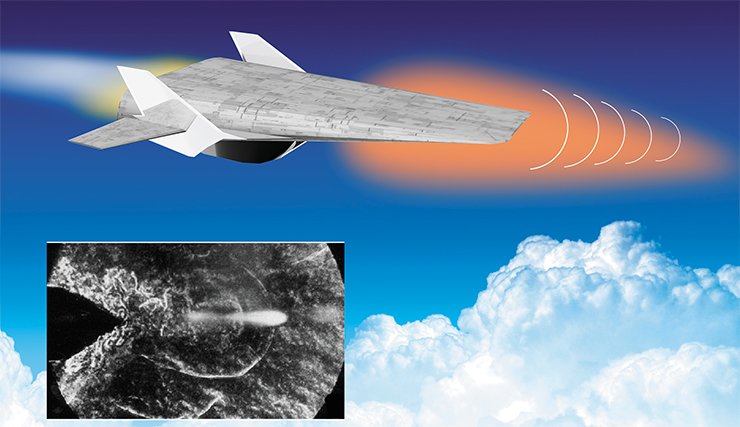
It was demonstrated by an example of a hypersonic gas flow around a tapered model airfoil that the lift-over-drag ratio and the lift force can be affected by forming a stepwise distribution of temperature in the free stream (which corresponds to a stepwise distribution of gas density). This effect can be achieved, for instance, with pulsed-periodic heating of the flow by a combination of laser and microwave radiation. The maximum lift-over-drag ratio is reached in the gliding mode, with the flight proceeding on the interface of high-density and low-density media.
Functional models
The efficiency of various methods of incoming air flow control can be verified by means of the so-called functional modeling. In this aspect, a flying vehicle, which is a complicated hierarchical structure, can be presented as a coupled set of various subsystems identified on the basis of functional features.
The mathematical model of a flying vehicle consists of a series of modules: aerodynamic characteristics, thrust and specific impulse of the engine, flight trajectory, functional constraints, and optimal control. Thus, the model reflects the functional characteristics and general relations between various elements without rigorous correspondence to particular devices.
Using such a model, we can estimate both the principal possibility of reaching the goal posed and particular characteristics (efficiency, critical regimes of engine operation, etc.). By changing the basic values of characteristics of individual elements, we can determine their influence on the functional properties of the system as a whole and establish the magnitude of admissible perturbations, i.e., work out requirements to the accuracy of measuring the corresponding parameters.
Functional modeling has the following specific feature: the synthesis and analysis of the object are performed with a small amount of initial information. It follows from here, first, that the mathematical model should be constructed through iterations, which implies permanent corrections of the process with due allowance for results obtained. Second, the model includes the minimum number of prescribed input parameters, which decreases the degree of uncertainty in finding the characteristics of the flying vehicle.
The second aspect stimulates the search for new, more generalized forms of presentation of functional properties of aircraft elements. Naturally, they should be consistent with a large variety of possible particular devices. The choice and development of these devices, however, will be the next stage of activities.
Combustion in a supersonic flow
The most important element of aerospace plane propulsion is the air-breathing engine (ramjet), which has been studied theoretically and experimentally by many researchers.
The concept of using the ramjet for hypersonic flight implies that fuel combustion in the engine duct should take place in a supersonic air flow. The amount of burning fuel should be sufficient for obtaining a needed thrust value. Ferri, a famous Italian physicist and the developer of the first supersonic wind tunnel, proposed several methods of fuel injection into the flow and described possible resultant flow patterns. There is no information, however, on their implementation in practice.
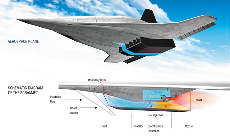
In general, the diagnostics of flows formed during fuel combustion is extremely difficult because of nonuniform distributions of flow parameters and nonequilibrium processes. Up to now, there are no reliable experimental data testifying that a supersonic flow in the engine duct is retained during its “heating” as a result of fuel combustion, in view of the fact that the static temperature of the gas should not exceed 2500–2700 °K. This constraint, which is important for hypersonic flight, is caused by the necessity of limiting the degree of dissociation of combustion products, because dissociation decreases the operability of the gas flow and, therefore, the engine thrust.
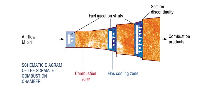
To determine the scramjet characteristics by available methods, it is necessary to specify a certain set of the controlling parameters, which depend on gas-dynamic and geometric parameters of the engine and are usually determined in experiments. Therefore, these methods are hardly useful in functional modeling, where it is necessary to determine the minimum set of the basic parameters whose changes in the course of system operation are comparatively small (and predictable).
Within the framework of this approach, ITAM researchers have constructed a functional mathematical model of propulsion, which allows the thrust coefficient and the specific impulse of the scramjet and of the rocket/scramjet combination to be estimated. The model takes into account that some part of the energy of combustion products will be used to control the external flow around the aircraft.
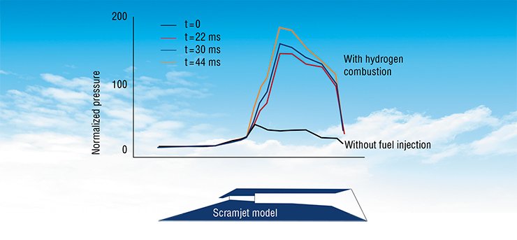
The estimates of efficiency of external flow control by means of air heating ahead of the vehicle show that the so-called Breguet** flight range increases significantly during the cruising flight at supersonic velocities (up to one third, depending on the flight Mach number) owing to the increase in the lift-over-drag ratio.
Fuel consumption for boosting with and without air heating ahead of the aerospace plane was compared for optimal flight trajectories where hybrid propulsion is used. The amount of fuel saved on the boost trajectory was 3 % of the takeoff mass of the aerospace plane. This means, first, that it will be easier to solve design problems. Second, it becomes possible to increase the payload appreciably.
In accordance to various estimates, the mass of payload inserted into the orbit is 3–5 % of the takeoff mass of the plane; this figure is commensurable with the predicted amount of fuel that can be saved by means of flow control. Thus, it is obvious that controlling the flow around the aerospace plane by means of incoming flow heating will be fairly effective both during cruising flight and during aircraft boosting.
Wanted: thermal protection
Last but not least: there are some particular problems that have to be solved in aerospace plane development. One of them is intense aerodynamic heating that has to be endured by aircraft structural elements for a long time, because the heat flux onto the aircraft surface is proportional to the flight velocity raised to the third power. Such a thermal effect is a real barrier that has to be surmounted in hypersonic planes design.
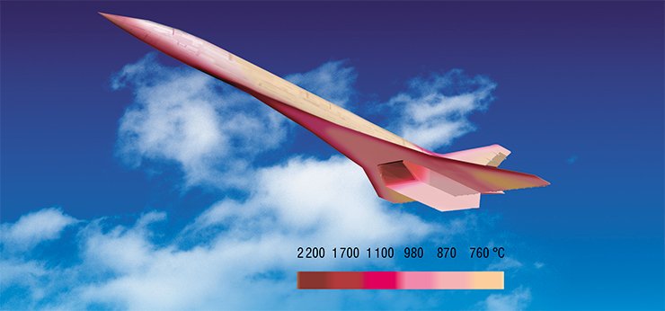
High temperatures of almost all areas of the vehicle surface eliminate the possibility of using conventional metals (aluminum, titanium, or steel). Possible methods of thermal protection of the vehicle surface are divided into passive and active methods, and also their combinations. Passive methods include, for instance, the use of disintegrating materials, emitting coatings, and coatings with low thermal diffusivity, which are characterized by moderate rates of temperature equalization. Methods of active thermal protection imply forced injection of the coolant to the hot surface, with possible penetration of the coolant into the boundary layer of the external air flow.
The method of thermal conversion of hydrocarbon fuel, which can partly replace liquid hydrogen, seems to be rather promising. The mixture of hydrocarbon fuel with water is supplied through channels under hot surfaces. Under the action of the heat flux, an endothermic reaction of formation of the synthesis gas (a mixture of carbon monoxide and hydrogen) occurs; this reaction proceeds with heat absorption.
The reaction is accompanied by intense convective motion of the medium, which ensures rather high values of the heat transfer coefficient and low thermal resistance between the medium and the heated wall. As a result, the surface temperature decreases. A “bonus” in this case is an increase in the fuel energy owing to absorption of the external heat flux.
Another tactical procedure of aerospace plane thermal protection is reduction of the area of surfaces that have to be protected from the action of high temperatures. A concept of a convergent inlet and a divergent nozzle, which are more compact than the corresponding conventional elements, was developed at ITAM SB RAS. A model of such a flying vehicle was tested in a hotshot wind tunnel of the institute at М = 7.8 with the engine operating on hydrogen, and experimental results coincided with numerical predictions.
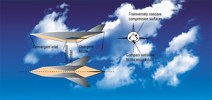
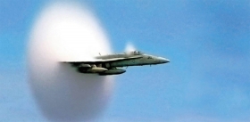
In a supersonic flight, the shock waves generated by the aircraft reach the Earth surface. The pressure difference across the shock wave generates the so-called sonic boom. The effect of the pressure difference on the eardrums can be rather painful; the sonic boom may be so strong that it can break window glass. The sonic boom intensity can be reduced by using a special configuration of the flying vehicle, by choosing appropriate flight trajectory and flight regime, and by active control of the shock wave structure in the vicinity of the flying vehicle.
Even the brief review presented here demonstrates the unprecedented complexity of single-stage aerospace plane development. A powerful stimulating factor for activities in this direction, however, is the exponential enhancement in the pace of conquering near space.
The entire set of activities (scientific research, design and development, prototype fabrication, experimental testing, and creation of maintenance structures) requires tremendous human, material, and financial resources. Apparently, the idea may come true only if many countries unite their efforts. But the final goal is worth it: further space conquest should facilitate successful and peaceful evolution of the mankind.
References
Burdakov V. P., Danilov Ju. I. Vneshnie resursy i kosmonavtika. M.: Atomizdat, 1976.
Georgievskij P. Ju., Levin V. A. Upravlenie obtekaniem razlichnyh tel s pomoshh’ju lokal’nogo podvoda jenergii v sverhzvukovoj nabegajushhij potok // Izv. RAN. MZhG. 2003. № 5. S. 154–167.
Latypov A. F. O matematicheskom modelirovanii letatel’nyh apparatov na jetape vyrabotki koncepcii // ChMMSS, 1979. T. 10, № 3. S. 105–110.
Latypov A. F., Fomin V. M. Ocenka jenergeticheskoj jeffektivnosti podvoda tepla pered telom v sverhzvukovom potoke // PMTF. 2002. T. 43, № 1. S. 71–75.
Latypov A. F. Ocenka jenergeticheskoj jeffektivnosti podvoda tepla pered telom pri polete s uskoreniem. Chast’ 1. Matematicheskaja model’ // Teplofizika i ajeromehanika, 2008. T. 15, № 4. S. 573–584. Chast’ 2. Matematicheskaja model’ razgonnogo uchastka traektorii.
Rezul’taty raschetov // Teplofizika i ajeromehanika, 2009. T. 16, № 1. S. 1–12.
Latypov A. F., Fomin V. M. Sposob raboty sverhzvukovogo pul’sirujushhego prjamotochnogo vozdushno-reaktivnogo dvigatelja i sverhzvukovoj pul’sirujushhij prjamotochnyj vozdushno-reaktivnyj dvigatel’ // Patent RF № 2347098, 2009.
Sabel’nikov A. V., Penzin V. I. K istorii issledovanij v oblasti vysokoskorostnyh PVRD v Rossii. M.: CAGI im. prof. N. E. Z hukovskogo, 2008.
* Minimum velocity necessary for launching the body to the Earth orbit
** The Breguet flight range is Br = VKI, where V is the flight velocity, K is the lift-over-drag ratio, and I is the specific impulse of the engine


